
Description
IGE-1108GS-120 – 8 Ports POE Ethernet Switch

Description
IGE-1108GS-120 is a The 8 ports PoE Ethernet Switch is a security surveillance ethernet switch which aims at Ethernet high definition surveillance and security system. The product fully combines the characteristics of security surveillance, provides fast packet forwarding ability and abundant backplane bandwidth, which ensures clear image and fluent transmission. ESD and surge protection, protect the information security, prevent the viral transmission and cyber attack, fully satisfy the Ethernet video security surveillance system and Ethernet project needs, security surveillance system and Ethernet project needs.
Applications
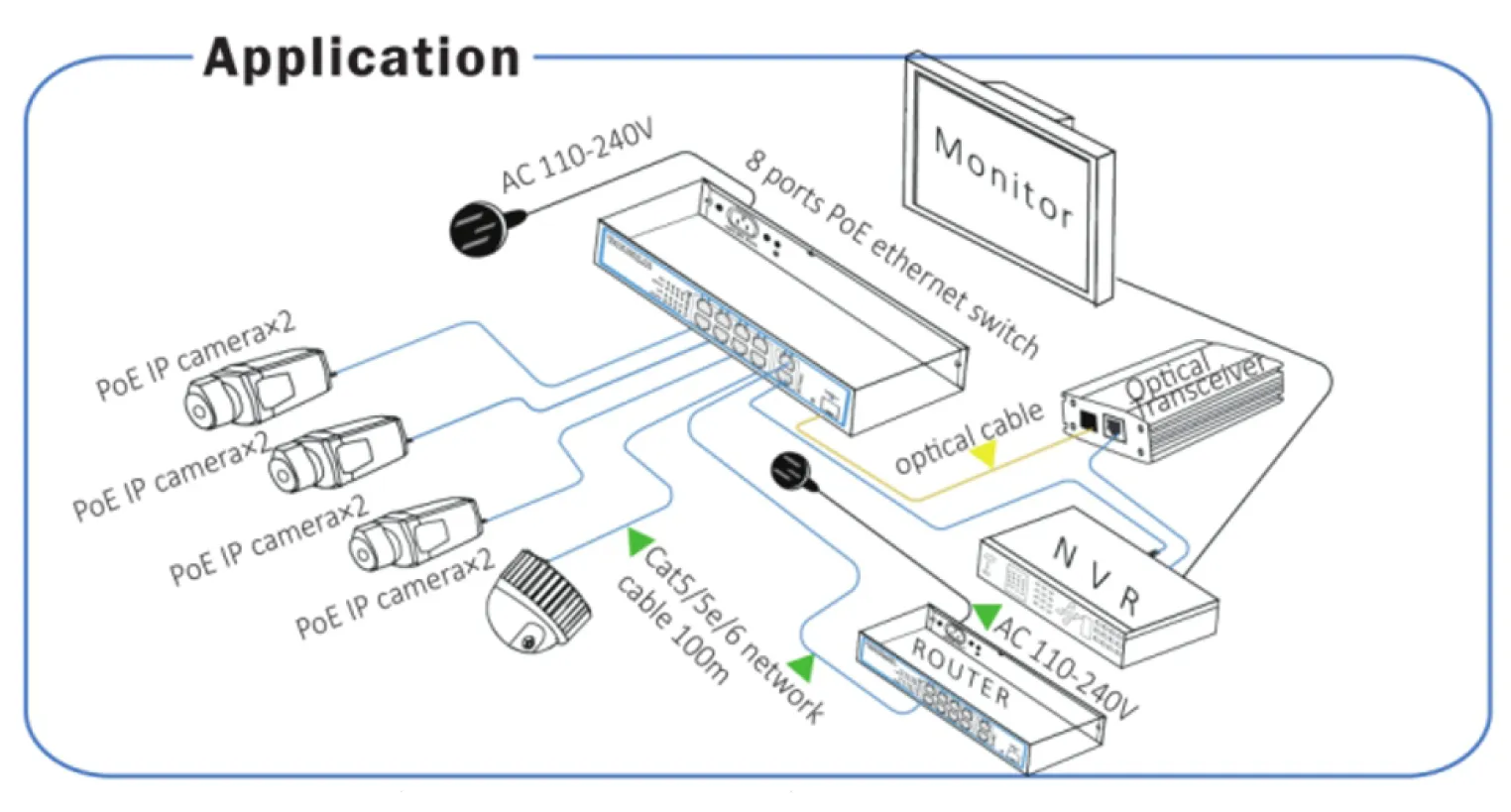
Feature
- Major ports: 8x 10/100/1000Mbps PoE ports, 2x 10/100/1000Mbps uplink port, 1x 10/100/1000Mbps SFP port, every port supports MDI/MDIX;
- Standard: IEEE802.3af/at, POE pin: 1/2+,3/6-(End-span), the remaining lines (4,5,7,8) can be used for other program;
- Protection: Excellent anti thunder, anti static and anti-interference ability.
- Smart design, with anti-theft lock, easy instalation.
- Operation: Plug amd Play, No Setting required.
Note: The transmission distance is related to the connected cable. We suggest standard Cat5e/6 network cable to make sure transmission distance can up to furthest!
Board Diagram

Note:
1) Device must be connected with lightning protection grounding,otherwise protection level will reduce;please use above No.20 wire to connect the grounding terminal.
2) Turn the dial switch for left, the equipment can enter surveilance mocule after providing equipment power.
Installation steps
Please check the following items before installation, if it is missing, please contact the dealer:
| 8 ports PoE Ethernet Switch | 1 pcs |
| AC power cable | 1 pcs |
| Accessory | 1 pcs |
| User manual | 1 pcs |
1) Please turn off the signal source and the device’s power before installing,
installation with power on may damage the device;
2) Use network cable connect PoE IP camera 1~8 downlink ports of product respectively;
3) Use a network cable connect equipment uplink port and NVR or computer;
4) Connect power adapter.
5) Check if the installation is correct, equipment is in good condition, the connection
is stable, then power on for system;
6) Ensure the Ethernet equipment with power on can work properly.
Specification
| Item | Description | |
| Power | Power Adapter Voltage | 110 – 240V AC |
| Consumption | 120W | |
| Network Connector | Network Port | 1~10 Port: 10/100/1000Mbps, 1~8: POE Ethernet Port |
| Uplink Port: two Ethernet 1000Mbps one SFP 1000Mbps | ||
| Transmission Distance AA | 1~8 Port: 100Mbps: 0~100m | |
| SFP: depends on the optical module | ||
| Transmission Medium | Cat5/5e/6 standard network cable | |
| Network Switch |
Network Standard | IEEE 802.1Q, IEEE 802.1u,IEEE 802.1x, IEEE 802.3ab |
| Switching Capacity | 22Gbps | |
| Forwarding Rate | 16.364Mpps | |
| MAC Table | 4K | |
| Power Over Ethernet | POE Standard | IEEE 802.3af/IEEE802.3at |
| POE Power Supply Type | End-Span(1/2+;3/6-) | |
| PoE Power Consumption | af≦15.4W, at≦30W (every port) | |
| LED Status Indicator VLAN/Ext end | POE Ethernet LED Indicator | Power: 1 red light indicates that the power normal work |
| POE:8 yellow lights indicate that the POE is power on | ||
| Ethernet: 11 green lights indicate that the Ethernet link and act; | ||
| Environmental | Working temperature | 0℃ ~ 55℃ |
| Relative Humidity | 20 ~ 95% | |
| Storage temperature | -20℃ ~ 70℃ | |
| Mechanical | Dimension (L x W x H) | 201 mm *120 mm *41mm |
| Color | Black | |
| Weight | 699g | |
| Stability | MTBF | >30000h |
Specification change will not be noticed.
(*) Made in China
Download Datasheet

Trouble Shooting
Please follow the steps if the equipment has trouble:
- Make sure the equipment is installed according to the manufactures installation guide.
- Confirm RJ45 cable order meets EIA/TIAS68A or 568B standard.
- Every PoE port can provide PoE equipment maximum power less than 30W, please do not connect the PoE equipment with power over 30W.
- Replace the equipment with a proper functioning 4 ports PoE Ethernet Switch to check if the equipment is damaged.
- Please contact your vendor if trouble still exists.
Plug Producing Method
Instruments to be used: wire crimper, network tester. Wire sequence of RJ45 plug should conform with EIA/TIA568A or 568B;
1) Please remove 2cm long the insulating layer, and bare 4 pairs UTP cable;
2) Separate the 4 pairs UTP cable and straighten them;
3) Line up the 8 pieces of cables per EIA/TIA 568A or 568B;
4) Cut off the cables to leave 1.5cm bare wire;
5) Plug 8 cables into RJ45 plug, make sure each cable is in each pin;
6) Use the wire crimper to crimp it;
7) Repeat above 5 steps to make the another end;
8) Use network tester to test the cable if it works;

Notice:
- When choose RJ45 make sure if one end is EIA/TIA568A, the other end should also be EIA/TIA568A.
- When choose RJ45 make sure if one end is EIA/TIAS68B, the other end should also be EIA/TIAS68B.
